Processing Examples after Molding
These are examples of how to fasten a SunForce™ molded product to a metal frame or other part. Taking advantage of the strength of the material itself, it can also be fixed with screws.
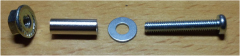
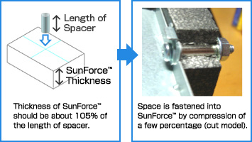
Fixing with nut, hollow spacer, washer and small screw.
Use spacer to maintain product structure and washer to enable stable fixing.
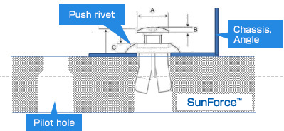
Plastics rivet
Nuts and bolts
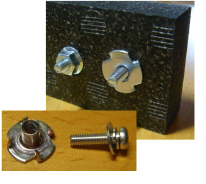
Fixing with tapping screw
Possible to tighten screws by direct tapping to SunForce™.
Tapping screw JIS type-1

- Fastening method
- Directly tap without pilot hole
- Length of screw
- 20mm
CAUTION)Please be sure to open pilot holes for M5 and above.For M4 or less, we recommend pilot hole to prevent cracking.
Adhesives
Fixing of SunForce™ using adhesive is also possible. Refer to table below for a list of adhesives recommended for use with SunForce™.
Appropriate adhesive varies depending on the usage environment, please contact us for details (contact us here).
| Adhesion to metal plates (Aluminium plates and SUS plates) | |||
|---|---|---|---|
| Grades of adhesive | Makers | Composition | Reference |
| Super-X2 | Cemedine Co.,Ltd. | Special polymer containing silyl group | Operating temp. -76~248deg.F |
| SX720W | Cemedine Co.,Ltd. | Acrylic polymer containing silyl group | UL94 V-0 |
| Acrylic Adhesives | Cemedine Co.,Ltd. | Acrylic polymer containing silyl group | |
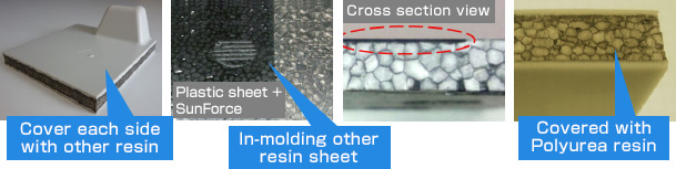
Secondary processing of SunForce™
Improve surface quality
Improve surface quality and flatness by pre-processing mold surface
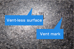
Partly vent-less surface is possible on thin plates
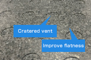
Improve flatness by using cratered steam vent
Improving surface quality, durability and waterproofing through the use of resin sheet